Once the z-axis hardware was in place on the printer, I needed to sort out the circuitry to make it work.
This is done using a computer for the control, which is hooked up over USB to an Arduino micro controller board. That board sends signals to an Easydriver board, which then sends the correct pulses to the pins on the motor.
This all sounds complicated but in reality it should be methodical set-up and a piece of cake to get it working. Theoretically!
The first thing to sort out was the wiring from the z-axis motor to the Easydriver to the Arduino.
Now, I’ll be the first to admit that my soldering is terrible. It’s so bad that I actually kept putting off doing the soldering for ages. Score one for procrastination.
The plan was to keep the soldering to a minimum and use jumpers and breadboards to connect everything up. The only soldering I’d need to do was actually on the motor itself.
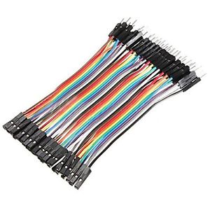
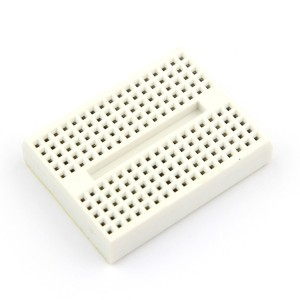
Through eBay I picked up some Dupont jumper wires and mini 170 point breadboards.
I separated four wires from the ribbon, snipped off the connectors at one end of the wires, then stripped back the plastic covering to reveal the wires inside. Next, I very carefully soldered the one wire to each of the four points on the z-axis motor.
Next step was to test it.
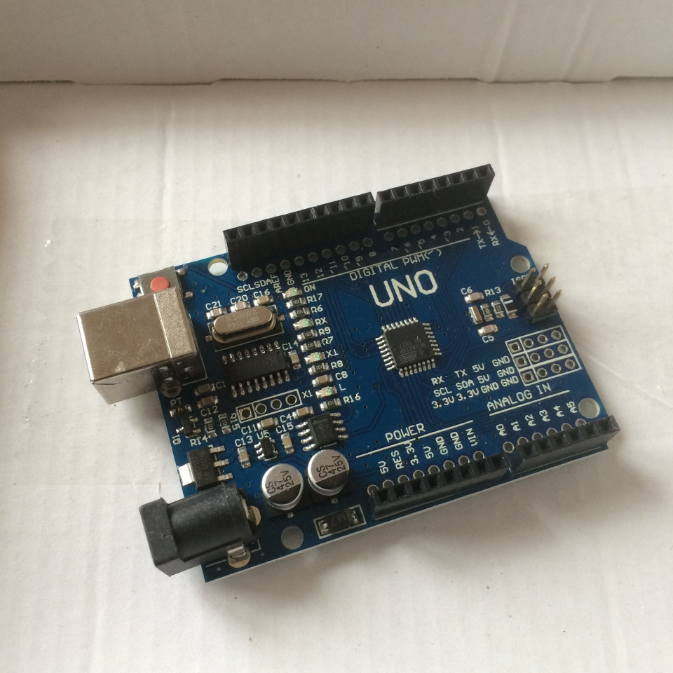
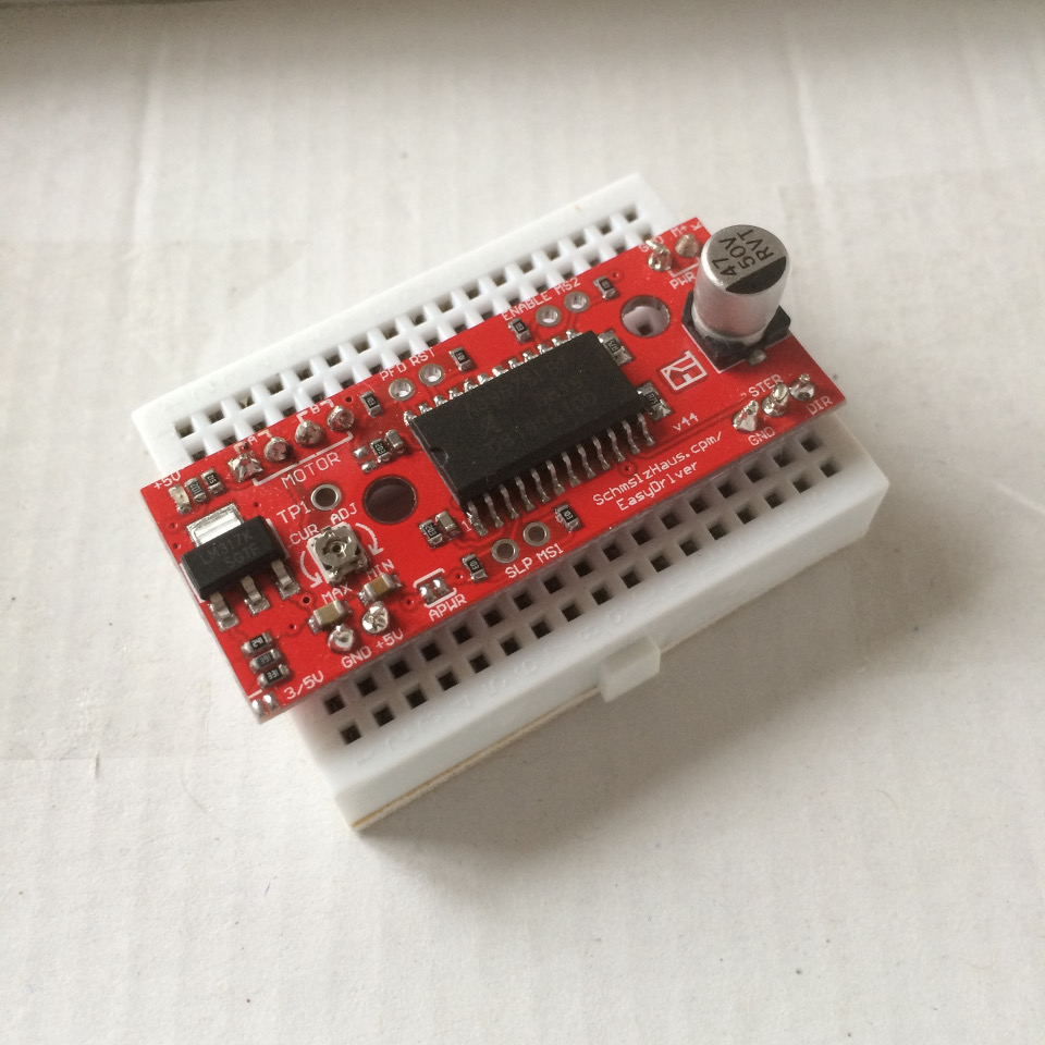
Through eBay I picked up an Arduino clone and an Easydriver board. Both had pins and sockets already soldered onto them.
With the z-axis motor still on the table, I connected a circuit in this configuration.
[circuit]
The motor works using two sets of coils (A & B) which run on the four wires soldered to it. There is normally a 0.5mm pitch FDC cable already attached but I could never find an adapter that would fit them. These four points on the motor need to be connected to the four stepper pins on the Easydriver.
The other Easydriver connections are mapped to a specific set of output pins on the Arduino. These pins are dictated by the GRBL software that is loaded onto it.
In order to control the easydriver through GRBL, it needs to be installed on the Arduino.
I plugged the Arduino into the laptop. Nothing happened.
As it’s a clone, the driver software that was installed with the Arduino development tools didn’t work with the new board. I figured out that the board was using a CH340 serial chip instead of regular one that is found on the original board.
I don’t have a problem with this. If I can get a comparable board for £4 instead of £16 which needs a little TLC then I’m good. Arduino is an open source hardware platform and people are supposed to make their own versions of the board.
I found these CH340/1 drivers online and after I disconnected the Arduino from the laptop usb, I installed them. Plugging the board in a second time showed that it was now recognised and the drivers were automatically mapped to create a new COM port. I just needed to use the Driver Manager screen to find out which one it was.
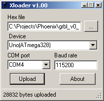
The GRBL software is downloaded as a HEX file (original), which needs to be written directly to the Arduino rather than installed through the Arduino Desktop Software. To send the hex file to the board I would use the XLoader program included in the GRBL zip.
I set the software to use COM4, 115200 baud transmission speed, selected the HEX file and pressed upload. At this point the program appeared to freeze but I could see the lights were flashing like mad on the Arduino. It’s unfortunate that it doesn’t have a progress bar to show how much data has been sent. I waited and after a short while the status line showed me that bytes had been written to the Arduino.
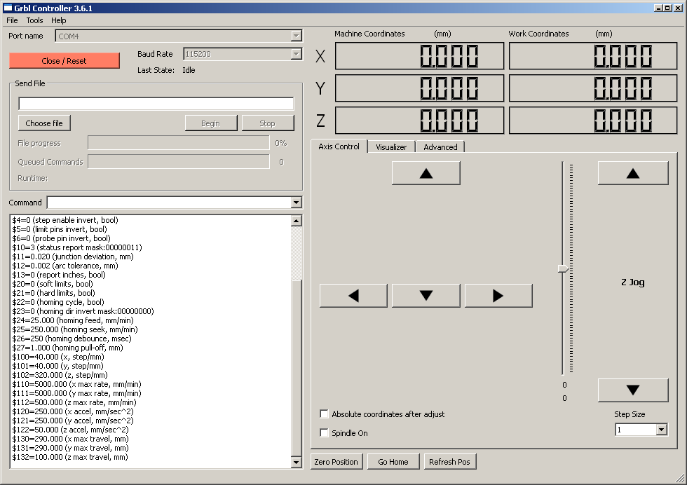
I closed the hex app at this point and loaded up a copy of GRBL Controller which is also included in the GRBL zip file.
I set the controller program to use COM4 and pressed OPEN, the info box filled with text from the GRBL controller and that the laptop was communicating with a correctly set-up Arduino board.
Using the z-jog buttons I tested that if I could cause the z-axis motor to turn.
It didn’t work properly, the motor juddered and wasn’t moving cleanly. I tracked this down to two problems.
- Not enough voltage.
- Incorrect wiring.
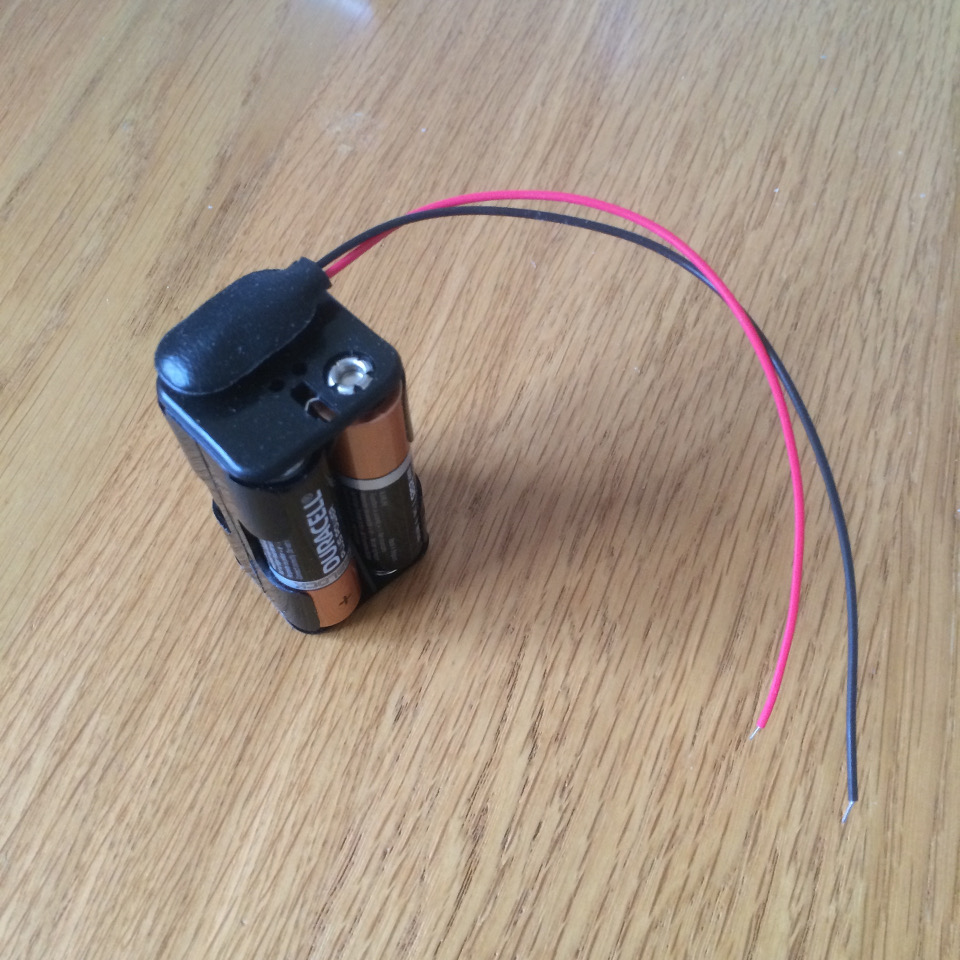
I altered the circuit to use a 4x AA battery pack to to give me 6v power for the motor. I don’t know if that’s too much but it’s not enough to use the 5v the Arduino chucks out.
As for the wiring, I swapped the wires around until I had the pairs of wires set up in the right orientation.
So that was that, I disconnected the circuit and re-attached the motor to the frame only to find that the wires were in the way. So I drilled a large hole in the middle of the upright MDF panel and fed the wires around the back. They weren’t long enough (I was considering mounting the arduino on the back of the upright), so I ordered longer some male to female Dupont cables from eBay to make an extension and left it at that.
When the cables arrived, I reconnected it all up based on what I thought was the right layout and it didn’t work.
I tried everything. I shuffled the wires around. I went back to Google to check I was wiring it up correctly. In the end I isolated the Easydriver from the motor, the Arduino was still working because I was able to connect to it ok. The fault had to be with the motor. I built this test circuit to see what polarity the motor wires were being driven with by the EasyDriver.
No problems with the EasyDriver, all four lights were switching and I could see different configurations of lights coming on. It had to be the motor.
Yup.. it was.
I’d wrapped the wiring in some electrical tape to keep it safe when I re-attached it to the frame. The wires had snapped clean off. I should have used hot-glue to seal it all up.
I ordered some replacement wire (solid core this time) and proceeded to remove these wires and attach the new ones. I made sure to make the long enough this time.
I was back in action. The z-axis was now fixed to the frame and I could control the motion up and down from the laptop.
Next page shows how I did my first print.

